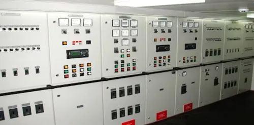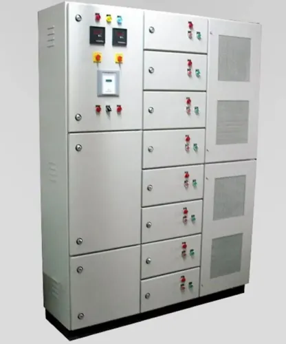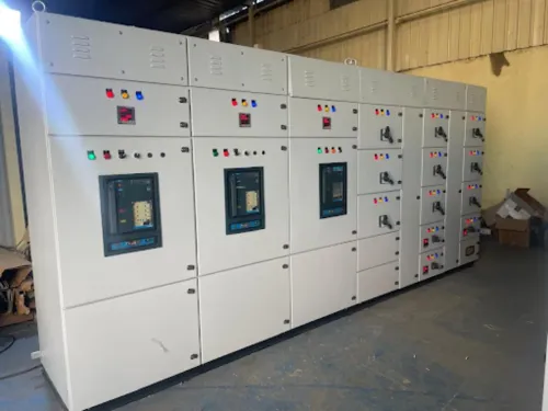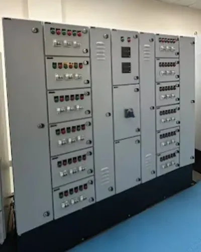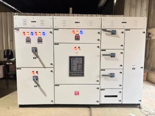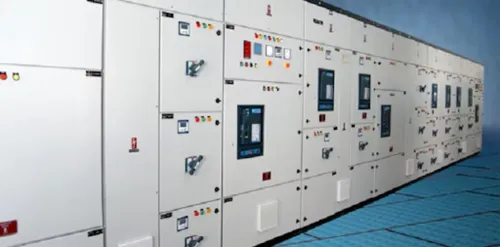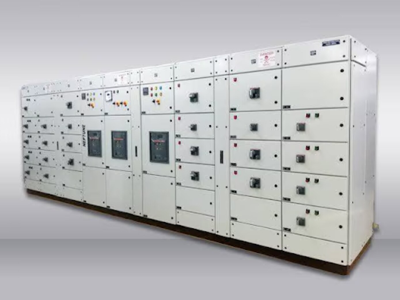
A PCC sits at the point where incoming electrical power becomes controlled plant distribution, so its design must match the transformer, fault level, loads, operating sequence and maintenance plan. By the end, you will be able to map each panel’s role, prepare a useful quotation brief, compare construction options and check whether a proposed assembly is adequately rated and verified.
Key takeaways
- Map transformer, MCC, motor and process-equipment connections before specifying the PCC.
- Calculate busbar, incomer and feeder ratings from demand, fault level and future expansion.
- Request short-circuit withstand data, routine test records and assembly compliance documents.
- Choose fixed, plug-in or drawout construction based on maintenance access and continuity needs.
Where a PCC Fits in the Plant Electrical Network
A PCC receives power from a transformer incomer or utility supply, protects and switches outgoing feeders, and distributes electricity across the plant. Its feeders supply MCCs, distribution boards, large motors and process equipment, making it the main branching point in the power distribution network.
MCC panel versus PCC panel is a distinction of purpose: the PCC distributes bulk power, while the MCC groups motor starters, contactors, overload relays and drives for controlled motor operation. A PCC is not automatically a single internationally defined product category; specify whether IEC 61439-2, UL 891 or UL 1558 applies.
| Panel | Primary job | Where it fits |
|---|---|---|
| PCC | Distributes incoming low-voltage power and protects feeders | Downstream of the transformer; upstream of plant loads |
| MCC | Starts, stops and protects motors | Near motor groups and process areas |
| Distribution board | Supplies smaller final circuits | Downstream of a PCC or MCC |
| Synchronising panel | Matches voltage, frequency and phase before paralleling sources | Between generators, utility and the main bus |
| APFC panel | Corrects power factor with switched capacitor stages | Connected to the main bus or a large load section |
The PCC’s fault rating is not its incomer breaker rating. Confirm the assembly’s SCCR or short-time withstand rating, because downstream drives, contactors, terminals and busbars can limit the complete panel. Mixer drives also require starting torque, jam conditions and duty cycle—not horsepower alone—to determine protection.
How to Build the PCC Size and Rating Schedule
Use the maximum demand, not the connected load alone, to set the PCC incomer. Calculate each load’s full-load current, apply the stated diversity factor to simultaneous operation, and compare the result with the transformer rating and upstream protection. Add motor-starting current, voltage drop, and continuous-load margins where the process requires them.
| PCC element | Calculation | Rating decision |
|---|---|---|
| Incomer | Maximum-demand current, transformer capacity, voltage drop and available fault current | Select continuous current, interrupting capacity and short-time withstand above calculated duties |
| Busbar | Actual simultaneous loading, assembly diversity factor, ambient temperature, enclosure ventilation, harmonic current and loaded-conductor arrangement | Select the tested thermal rating; do not add every feeder rating mechanically |
| Feeder | Individual load current, starting current, cable ampacity, voltage drop and prospective fault current at the feeder terminals | Select conductor, breaker frame, trip settings and interrupting rating together |
Calculate prospective short-circuit current at the PCC and at each feeder. The feeder breaker’s interrupting rating does not prove the assembly’s SCCR or short-time withstand; the weakest component and tested device combination control.
In a three-phase, four-wire PCC, triplen harmonics from nonlinear single-phase loads add in the neutral. Check neutral, transformer and busbar heating from harmonic current rather than sizing them from fundamental phase current alone. Record spare ways and future load separately from present demand.
What to Put in a PCC Manufacturer’s Quotation Brief
Send every bidder the same engineering brief; otherwise a low quotation may simply omit scope. Include the single-line diagram, system voltage and frequency, transformer rating, connected and maximum demand, feeder schedule, spare ways, cable sizes, and installation location.
- State the fault level at each source, earthing arrangement, phase sequence, available short-circuit current and required withstand rating.
- Define the protection philosophy: selective coordination, earth-fault protection, instantaneous-trip limits, interlocking and operating access.
- Specify metering, CT ratios and accuracy class, cable-entry direction, enclosure IP rating, indoor or outdoor duty, ambient temperature and internal separation.
- Identify generators, automatic transfer equipment, drives, APFC equipment and nonlinear single-phase loads. Ask for neutral sizing that accounts for triplen harmonics, not only fundamental current.
| Quotation item | Put in your brief | Request in the quotation |
|---|---|---|
| Standard | IEC 61439-2, UL 891, UL 1558 or UL 845 | Exact assembly standard and verification documents |
| Construction | Fixed, plug-in or drawout; Form 2, 3 or 4 | Layout, maintenance access and segregation details |
| Sources | Utility, generator or redundant incomers | Fault current, neutral switching, phase sequence and transfer interlocks per source |
| Drives | Drive ratings, bypass, reactors, filters and cable lengths | Harmonic, EMC, motor-insulation and drive fault-current assumptions |
Give this identical schedule to Maxwell Tech Solutions Pvt Ltd and every competing manufacturer; then compare exclusions, assumptions and test evidence rather than the headline price.
Related product
 | Electrical Control Panel Manufacturer in India, Pune, Pimpri Chinchwad | Maxwell Tech Solutions Pvt. Ltd. Maxwell Tech Solutions Pvt. Ltd. View product → |
Selecting Protection, Metering and Drive-Ready Equipment
Use the device that matches the fault, load and isolation duty; a larger breaker is not automatically safer or better coordinated. Specify metering separately, including measurement accuracy, CT ratio, energy register and communication protocol.
| Option | Use | Key limitation |
|---|---|---|
| ACB | Main incomer or high-current feeder | Needs coordination settings and space for maintenance |
| MCCB | Medium-current outgoing feeder or motor supply | Confirm interrupting rating, trip curve and adjustability |
| Switch-fuse | Compact feeder protection with visible isolation | Fuse replacement interrupts service |
| Contactor | Frequent motor starting, stopping or reversing | Not a short-circuit protective device |
| Protection relay | Overload, earth-fault or motor-specific protection | Requires correctly selected CTs and settings |
| Surge protection | Diverts transient overvoltage to earth | Requires short connections and backup protection |
A drive-fed PCC needs more than a motor breaker. Check the drive’s input short-circuit rating, install an input reactor or DC choke where required, and coordinate EMC filtering, bypass interlocking, output-cable length and motor insulation.
For mixer or agitator drives, base selection on:
- Starting and breakaway torque
- Batch viscosity and acceleration time
- Stall, jam and reversing duty
- Gearbox ratio and duty cycle
- Simultaneous operation of other loads
Record the resulting panel SCCR; a high-rated incoming breaker does not raise the SCCR of downstream contactors, drives or busbars.
Fixed, Plug-In or Drawout: Choosing the Construction
Fixed construction costs least and occupies less space, but isolating a feeder means switching off the PCC section and proving dead before opening it. Plug-in PCC units improve isolation speed: you switch off the feeder, remove the plug-in unit, and fit a shutter or blanking arrangement.
Drawout switchgear costs most, yet a breaker can move from connected to test, disconnected and removed positions without disturbing the busbar.
| Option | Cost | Isolation speed | Maintenance access and operational risk |
|---|---|---|---|
| Fixed construction | Lowest; simplest assembly | Slowest; cables and terminals remain in place | Restricted access, with greater exposure during work and a longer outage |
| Plug-in PCC | Mid-range; requires compatible busbar and units | Faster; unit removal limits the isolated area | Better feeder access, but incorrect insertion or weak contact engagement creates risk |
| Drawout switchgear | Highest; adds chassis, shutters and interlocks | Fastest; withdraw the breaker or starter | Best access and shortest replacement outage, but interlock failure, racking errors and higher maintenance complexity matter |
Specify Form 2, Form 3 or Form 4 separately from the mechanism. Form 2 separates busbars from functional units; Form 3 separates units from each other; Form 4 also segregates outgoing terminals. These barriers reduce accidental contact and fault spread, but none makes energized work arc-resistant.
Check the applicable IEC 61439-2, UL 891, UL 1558 or UL 845 basis before comparing quotations.
Proving Fault Withstand and Assembly Compliance
A completed PCC is compliant only when the assembly, not just its individual breakers, has documented design verification. Specify IEC 61439-1 and IEC 61439-2 in the purchase documents, then obtain the manufacturer’s verification evidence for the exact construction, ratings and protective-device combinations.
Check these records before acceptance:
- Short-circuit verification showing the busbar and enclosure withstand the specified Icw short-time current and Ipk peak current for the stated duration.
- Verification that each incomer and feeder can interrupt the prospective fault current at its terminals; a breaker’s interrupting rating does not establish the PCC’s assembly short-circuit rating.
- Temperature-rise, dielectric, clearance and creepage verification for the assembled layout, including joints, barriers and cable compartments.
- Protective-circuit continuity and mechanical-operation checks, including drawout shutters, interlocks and earth connections where fitted.
- A coordination study using time-current curves, with upstream and downstream settings proving selectivity or documenting the permitted backup-protection condition.
The final dossier should match the delivered PCC’s busbar size, compartment arrangement, breaker models, trip units and fault level. Test the completed assembly for insulation resistance, dielectric withstand, phase sequence and functional tripping; record results against identifiable panel and device serial numbers.
If the source includes a generator or automatic transfer scheme, repeat the fault and coordination review for each source.
Frequently asked questions
Where does a PCC fit in a plant electrical network?
A PCC receives power from a transformer incomer or utility supply, then distributes protected outgoing feeders to MCCs, distribution boards, large motors and process equipment.
What information should you include in a PCC manufacturer’s quotation brief?
Include the single-line diagram, incoming voltage and fault level, connected and maximum demand loads, feeder list, cable details, metering requirements, enclosure conditions, form of separation and future expansion allowance.
How do you choose between fixed, plug-in and drawout PCC construction?
Choose fixed construction for simpler installations, plug-in construction when feeder changes and isolation matter, and drawout construction when maintenance speed and service continuity justify added cost and space.
Which documents prove PCC fault withstand and assembly compliance?
Request the declared short-circuit withstand rating, design verification or type-test evidence, routine test reports, protection coordination information, wiring diagrams and the completed inspection dossier.