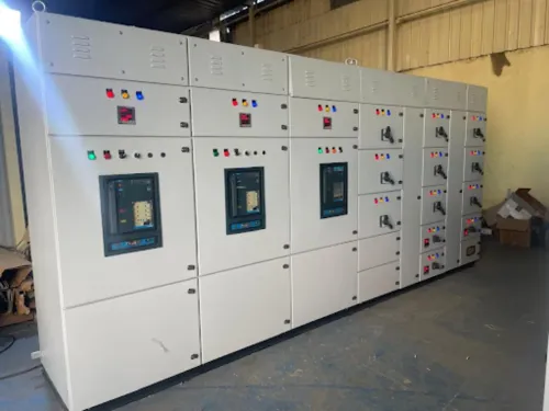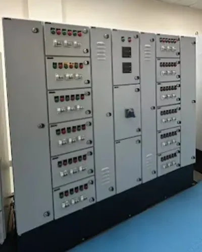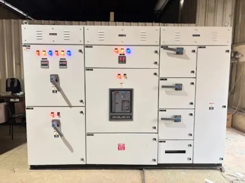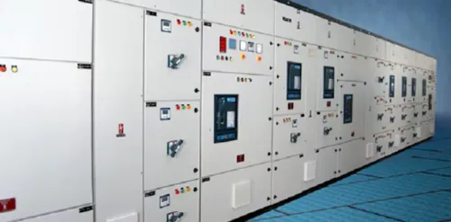
An HT panel manufacturer is responsible for far more than fabricating a metal enclosure and installing a circuit breaker. By separating voltage-class requirements, design evidence, fault performance, protection studies, testing, and lifecycle support, you can compare quotations on engineering value rather than on price or vague claims such as “heavy-duty.”
Key takeaways
- Match the panel to the system voltage, not the motor nameplate.
- Request switchgear ratings, type-test reports and compliance documents before comparing offers.
- Give fault levels, load data and protection requirements to prevent an underspecified design.
- Confirm factory testing, installation scope and lifecycle support before placing the order.
Confirm the Manufacturer’s Scope and the Correct Voltage Class
An HT panel is the right starting point only when your system operates above 1 kV; an LT PCC, MCC or motor-control assembly serves systems up to 1 kV. Match the panel to the incoming utility voltage, transformer secondary and distribution architecture, not to the motor nameplate alone.
Choose an 11 kV switchboard for an 11 kV network, a 22 kV switchboard for a 22 kV supply, and a 33 kV switchboard for a 33 kV network. Using the wrong voltage class creates insulation, clearances, protection and utility-approval problems that a higher current rating cannot fix.
Check that the HT panel manufacturer can provide all of these items:
- Single-line review, insulation coordination, fault-level calculations and protection studies for your actual installation
- Busbar fabrication, metal-enclosed construction, circuit-breaker integration and enclosure manufacture
- Protection relays, instrument transformers, metering, interlocks, auxiliary supply and cable-termination design
- Routine testing, inspection records, drawings, protection settings and operation manuals
- Site installation, cable termination, commissioning, energisation support and after-sales spares
- Evidence for the proposed construction under IS/IEC 62271-200 and the installed breaker under IS/IEC 62271-100
Ask whether the submitted design is a verified assembly or a modified arrangement. For an LT assembly, IEC 61439 design verification applies to the actual construction; changing busbars, compartments or components outside that verified system can invalidate the evidence. The same discipline matters when comparing an LT solution with an HT panel.
Compare the Switchgear Design, Ratings and Compliance Evidence
Do not accept “IEC compliant” as a design comparison. Ask each manufacturer for the exact IS/IEC 62271-200 classification, the IS/IEC 62271-100 breaker rating, and certificates covering the proposed construction. Compare the ratings with the calculated RMS fault current, X/R ratio, transformer and motor contributions, not with a nominal kA figure alone.
| Feature | Stronger proposal | Evidence to request |
|---|---|---|
| Loss of service continuity | LSC2 rather than LSC1 where the process must remain energised during access | IS/IEC 62271-200 test documentation |
| Partition class | PM for metal partitions around live compartments; PI for insulating partitions | Construction drawings and classification report |
| Internal arc classification IAC AFL AFLR | IAC AFL for front and lateral access, or IAC AFLR when rear access is required | Test certificate naming the enclosure, pressure-relief path and installation arrangement |
| Fault withstand | Rated short-time withstand current with duration, peak withstand current, and making and breaking ratings matched to the study | Datasheet, calculation and breaker certificate |
Treat IAC as an installation-specific result: a tested enclosure does not automatically protect a different room, cable route or pressure-relief arrangement. Check the proposed IP rating against IEC 60529, then verify busbar material, continuous current, insulation level, breaker technology and auxiliary supply.
Request these documents before comparing prices:
- Single-line diagram and GA drawings showing compartments, shutters and cable access
- Type-test certificates for the offered design, plus routine-test format for every panel
- Protection settings basis covering motor starting, transformer inrush, earth-fault sensitivity and breaker clearing time
- A statement identifying every deviation from the tested construction
Give the Manufacturer Complete Inputs and Read the Technical Offer Line by Line
A technically neat quotation can still fail because the manufacturer received incomplete inputs. Send the single-line diagram, load schedule, fault-level study and protection-coordination study, then identify every transformer, motor, mixer, compressor, drive, standby source and future feeder connected to the HT bus.
Provide these project conditions before pricing:
- State nominal voltage, frequency, earthing method, utility fault contribution, transformer impedance, X/R ratio, motor contribution and required short-circuit duration.
- Give starting data: locked-rotor current, acceleration time, repeated-start pattern, voltage-dip limit, regenerative energy, harmonic current, bypass arrangement and ride-through requirement.
- Specify altitude, ambient temperature, humidity, dust, corrosive gases, condensation, washdown, vibration, seismic exposure and indoor or outdoor solar loading.
- For hazardous areas, state the zone, gas or dust group, temperature class, equipment protection level and required concept, such as Ex p, Ex d or Ex e.
Read the offer against the documents below, not only its total price.
| Document | Check line by line | Incomplete or invalid if |
|---|---|---|
| Fault-level study | RMS current, X/R ratio, peak current and transformer and motor contributions | The kA figure has no duration or peak value |
| Protection-coordination study | Relay settings basis, inrush restraint, motor starting, cable limits, earth-fault sensitivity and breaker clearing time | It solves nuisance tripping by simply raising pickup |
| Arc-flash study | Method, working distance, enclosure, electrode orientation and clearing-time assumptions | It treats short-circuit rating as incident-energy proof |
| Technical offer | Busbar, breaker, relay, CT, auxiliary supply, cable entry, derating and test scope | Ratings omit environmental or altitude conditions |
Require calculations for starting voltage dip and harmonics where drives or large motors are present. A panel adequate at full-load current can still trip during acceleration or leave downstream protection non-selective.
Verify Fault Performance, Protection Coordination and Power-Quality Behaviour
Approve the panel only after its fault rating matches the calculated prospective current at the installation point. Compare the RMS fault current and X/R ratio with the breaker’s making and breaking capacity, rated short-time withstand current, and peak withstand current. A nominal kA figure without a duration is incomplete.
The manufacturer must provide a coordinated protection study, not a relay model number. It should show time-current coordination, breaker clearing time, transformer inrush restraint, earth-fault sensitivity, cable thermal limits, and motor-starting behaviour. Raising instantaneous or short-time pickup to stop nuisance trips can sacrifice selectivity and increase incident energy.
Check instrument transformers as closely as the relay. Confirm CT ratio, burden, accuracy class, remanence behaviour, protection duty, and CT knee-point voltage. CT saturation during a close-in fault can defeat transformer differential protection or delay discrimination through a numerical overcurrent relay, even when the settings appear correct.
Require project-specific evidence before approval:
- An arc-flash study stating prospective current, clearing-time assumptions, working distance, enclosure configuration, and electrode orientation.
- Motor and drive calculations covering locked-rotor current, acceleration time, voltage dip, repeated starts, harmonic current, regenerative energy, and bypass or ride-through behaviour.
- Factory test records for CT polarity and ratio, relay secondary injection, breaker timing, trip-circuit supervision, interlocks, metering, communications, and simulated trips.
The proposed panel must remain stable during direct-on-line or reduced-voltage starting and normal variable-frequency-drive operation. Verify those cases at the bus, not only at full-load current.
Judge Testing, Installation Capability and Lifecycle Support Before Awarding the Order
A factory acceptance test witnessed only as a visual inspection does not prove that the panel will trip, interlock or communicate correctly during a fault. Award the order only when the manufacturer commits to documented testing, site commissioning and support after energisation.
1. Request the factory acceptance test (FAT) procedure before approval. It should separate routine tests from project-specific checks: insulation resistance or dielectric testing, wiring continuity, interlocks, breaker timing, CT polarity and ratio, relay injection, trip-circuit supervision, remote-control logic, metering, communications and simulated protection trips.
2. Demand a routine test certificate for every manufactured assembly, with serial-number traceability for breakers, CTs, relays and busbar materials. For any associated LT assembly, ask how its IEC 61439 design verification covers temperature rise, short-circuit withstand, clearances, creepage, dielectric strength and mechanical operation; an uncontrolled substitution or field modification can invalidate that basis.
3. Put site responsibilities in the purchase order. Specify installation supervision, cable termination checks, torque records, insulation tests, relay settings, secondary injection, breaker operation, protection coordination, SCADA point checks and energisation support. For hazardous areas, require certification for the actual enclosure and cable-entry arrangement, not merely individual Ex glands or switches.
4. Secure after-sales support in writing: guaranteed support period, spare-breaker and relay lead times, critical spares, firmware and software access, end-of-life notification, battery or capacitor replacement intervals and remote diagnostics. Maxwell Tech Solutions Pvt Ltd should be assessed against these deliverables, not its product catalogue alone.
Frequently asked questions
When do you need an HT panel instead of an LT panel?
Use an HT panel when the system operates above 1 kV. For systems up to 1 kV, specify an LT PCC, MCC or motor-control assembly. Check the incoming utility voltage, transformer secondary and distribution architecture.
What should you compare between HT panel manufacturers?
Compare the switchgear design, voltage and current ratings, short-circuit withstand ratings, protection scheme and evidence such as type-test reports and compliance documents.
What information should you give an HT panel manufacturer?
Provide the single-line diagram, incoming voltage, transformer data, connected and running loads, fault level, motor details, protection requirements, site conditions and installation constraints.
How can you verify an HT panel’s fault performance and protection?
Check the prospective short-circuit level against the panel’s short-time and peak withstand ratings, then review protection coordination, relay settings and power-quality behaviour.
What support should you confirm before awarding the order?
Confirm factory acceptance testing, inspection records, installation and commissioning responsibilities, documentation, spare parts, training, warranty terms and service response arrangements.