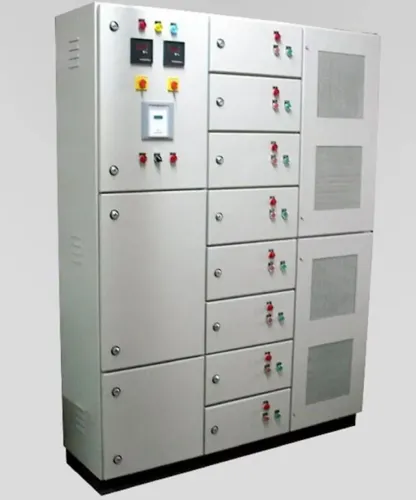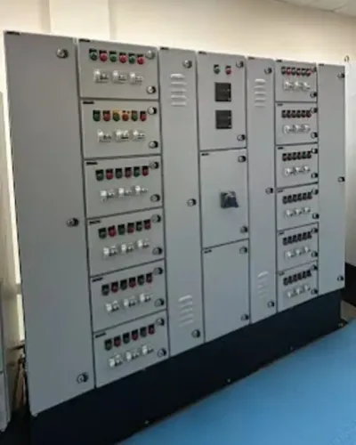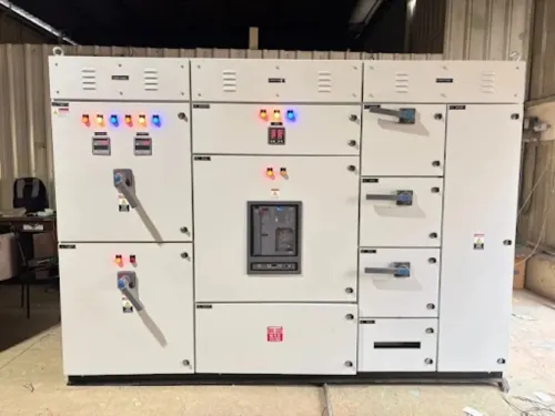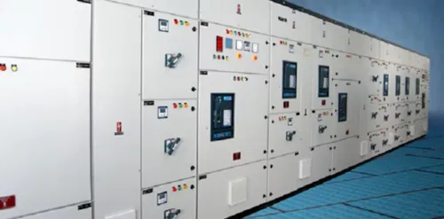
An LT panel sits between the transformer or utility incomer and the equipment that consumes power, so a mistake in its design can affect every production line downstream. By the end, you will know how to review the distribution design, protection scheme, earthing, verification records and manufacturer handover documents before approving an assembly.
Key takeaways
- Match breaker ratings to the load schedule and prospective fault current.
- Use segregation, isolation and interlocks to contain faults safely.
- Verify insulation, continuity, protection settings and earthing before energising.
- Collect approved drawings, test reports and maintenance instructions at handover.
What an LT Panel Controls in a Factory Distribution System
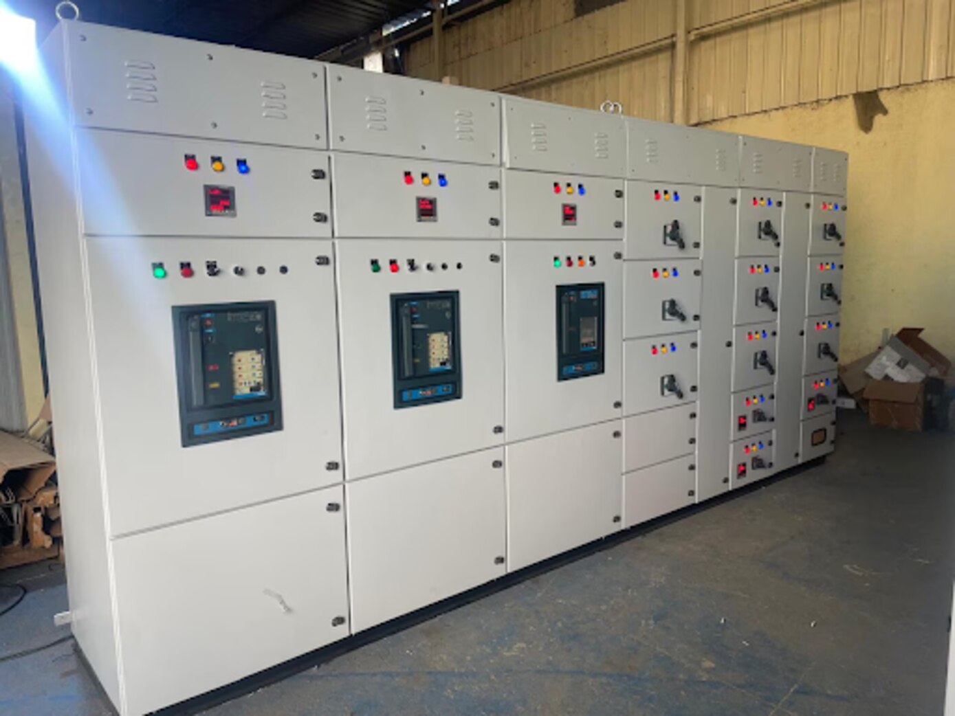
An LT panel is a low-voltage switchgear and controlgear assembly installed downstream of a transformer or utility incomer. It receives power at the factory’s low-voltage level, controls the main busbars and distributes protected supplies.
The power path runs from the transformer or service entrance to the main LT panel, through outgoing feeders, then to sub-distribution boards and final loads such as motors, heaters, lighting and sockets. A safe design identifies the actual voltage, earthing arrangement, load type and downstream responsibility instead of trusting the panel label.
A PCC panel comparison should focus on function and location:
| Term | Function and location |
|---|---|
| HT panel | Handles the higher-voltage side before transformation; it is upstream of the LT system. |
| Main LT panel | Controls and distributes the transformer’s low-voltage output to plant feeders. |
| PCC panel | Describes power-control and distribution; the main LT assembly may perform this function. |
| MCC | Concentrates motor feeders, contactors, overload relays and motor-protection equipment. |
| DB | Distributes power to smaller final circuits downstream. |
| PLC panel | Houses PLCs, I/O, relays and control hardware; it is not the plant’s primary power-distribution point. |
| APFC panel | Switches capacitor stages to correct power factor. |
The correct assembly therefore depends on where it sits, what it supplies and which protective boundary it owns.
How the Manufacturer Turns the Load Schedule into a Safe Design
The load schedule determines the panel’s ratings, spare capacity and physical arrangement before fabrication begins. Review connected loads, calculate maximum demand with a documented diversity factor, separate continuous from intermittent loads, and complete a motor starting analysis covering starting current, starting voltage drop and duty cycle.
Request these inputs before sizing:
- Transformer kVA and impedance; utility fault-level data; prospective short-circuit current at the panel; system voltage and frequency.
- Ambient temperature, altitude where relevant, cable lengths, installation methods, motor data, harmonic-producing loads and the required future expansion margin.
Use this sizing sequence:
- Calculate each motor’s full-load current from I = P ÷ (√3 × V × efficiency × power factor), using the actual three-phase voltage.
- Select the incomer and busbars for continuous current after derating for ambient temperature, grouping and enclosure heat dissipation.
- Check cable ampacity and voltage drop during running and motor starting.
- Select each outgoing protective device for both the cable and its load.
- Verify that breakers, links, busbars, supports and the complete assembly withstand the available fault current for the specified fault type and duration.
A 630 A incomer does not reveal whether the site fault level is 25 kA or 50 kA. Obtain that value from the transformer and distribution system.
Finally, choose IP rating, cable-entry arrangement and internal segregation with maintenance in mind. Compact construction saves space but restricts cooling and access; larger separation improves serviceability while increasing enclosure size and cost. Calculate losses from breakers, contactors, drives, transformers, power supplies and busbars before accepting the nominal current rating.
How Protection, Isolation and Earthing Prevent One Fault from Becoming a Plant Shutdown
Protection coordination is a system-level task linking the ACB or MCCB incomer, feeder MCCBs, motor-protection devices, contactors, overload relays and downstream fuses. Review time-current curves, set adjustable trips, and use manufacturer coordination tables where required; progressively smaller current ratings alone do not prove selectivity.
Check these protection and isolation functions before approval:
- Provide short-circuit protection, overload protection and earth-fault protection for each circuit, with under-voltage release and shunt trip where the operating and emergency-isolation strategy requires them.
- Match the assembly’s short-circuit rating to the calculated prospective fault current, fault type and clearing duration. A breaker interrupting rating does not prove busbar, link, support or enclosure withstand; verify the tested or documented assembly rating and back-up combination.
- Fit door interlocking, mechanical shutters over accessible live parts and phase indication. Bond the protective-earth bar, doors, removable metalwork and gland plates; terminate cable armour correctly and keep neutral and earth conductors separate where the earthing design requires it.
- Size the neutral for triplen harmonics from switch-mode supplies, LED loads, drives and IT equipment; lightly loaded phases do not justify a reduced neutral.
- For drives, check harmonics, true power factor, leakage or common-mode current, heat, EMC cable routing and residual-current-device compatibility. Coordinate SPDs with voltage, earthing configuration, short-circuit protection, bonding and conductor routing.
- Complete an arc-flash assessment. Current-limiting devices and shorter clearing time reduce incident energy, but working distance and enclosure geometry still matter.
What the Manufacturer Must Verify Before the Panel Reaches Site
Before shipment, demand evidence that the complete assembly—not merely its breakers or empty enclosure—meets IEC 61439. Request design verification records for:
- Temperature rise, using actual losses from breakers, contactors, drives, transformers, power supplies and busbars.
- Dielectric properties, short-circuit withstand, protective-circuit continuity, clearances, creepage distances and mechanical operation.
- The declared assembly rating, including rated current, short-circuit withstand and achieved IP rating.
Request routine verification records for the specific panel: wiring and component identification, protective-circuit continuity, insulation or dielectric testing, functional operation, interlocks and recorded protective-device settings. A visual inspection cannot prove correct trip settings or control logic; require a factory acceptance test linked to approved drawings, an I/O and protection test schedule, and recorded results.
Confirm that the IP rating applies to the completed assembly in its installed condition. Cable glands, damaged seals, ventilation openings, filter fans, unused knockouts and field drilling can reduce it. Heat calculations must include enclosure size, orientation, ambient temperature, ventilation and grouped equipment, not only nominal current.
Ask which form of internal separation is provided and why. Separation can limit accidental contact and simplify maintenance, but it increases size, cooling difficulty, cost or access constraints.
Evaluate Maxwell Tech Solutions Pvt Ltd like any LT panel manufacturer: match its proposed rating, thermal design, protective coordination and test records to your project data, rather than accepting the requested panel type as proof.
Which Drawings and Handover Records Make the Installation Safe to Operate
A safe handover pack lets the installer, commissioning team and maintenance staff prove what was built, not guess from labels. Require the approved revision of every drawing, including:
- Single-line diagram showing the transformer or utility incomer, main LT panel, bus sections, feeders, sub-distribution boards, protective devices and earthing arrangement
- GA drawing showing dimensions, working access, ventilation, cable entries and segregation
- Power and control schematic, terminal schedule, cable schedule and bill of materials
- Device data sheets, busbar and enclosure ratings, short-circuit rating, and the supporting test or coordination report
- Final breaker trip settings, torque records, insulation-resistance and earth-continuity results, FAT records, SPD details, and neutral and PE arrangements
The commissioning boundary must name the responsible person for each action.
| Role | Responsibility to record | Why it matters |
|---|---|---|
| Installer | Terminate cables and armour; bond glands | Prevents open PE paths and EMC faults |
| Commissioning team | Isolate and test upstream supply; confirm phase sequence and earthing | Stops energisation with reversed phases or unsafe fault paths |
| Protection engineer | Apply settings and verify coordination | A smaller breaker rating alone does not prove selectivity |
| Authorised person | Approve energisation | Establishes a controlled handover |
Replacing a breaker, adding a feeder, drilling a gland plate, changing settings or bypassing an interlock can alter fault, thermal, EMC or ingress performance and invalidate verification. Voltage, fault level, enclosure rating, segregation, neutral sizing and Indian installation requirements depend on the project and applicable rules; no single specification suits every LT assembly.
Frequently asked questions
What does an LT panel control in a factory distribution system?
It receives low-voltage power from a transformer or utility incomer, controls the main busbars and distributes protected supplies to factory loads.
How does a manufacturer convert a load schedule into an LT panel design?
The manufacturer reviews connected and maximum demand loads, motor starting requirements, feeder ratings, fault level, spare capacity and the required protection settings before selecting the panel arrangement.
How do protection, isolation and earthing limit the impact of a fault?
Correctly rated breakers interrupt fault current, isolators create a safe disconnection point, segregation limits damage between circuits, and protective earthing provides a low-impedance path for fault current.
What records should you receive before operating the panel?
Request the approved single-line diagram, general arrangement drawing, control and wiring diagrams, terminal schedule, protection settings, test reports, equipment manuals and maintenance instructions.