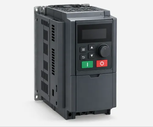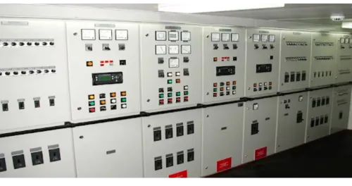
A 50 Hz supply does not by itself deliver the speed, torque response or repeatability that every industrial process needs. By the end, you will know how to match drive control, capacity, feedback, braking, instrumentation and installation requirements to the motor and the duty it performs.
Key takeaways
- Match drive size to motor current, torque demand and overload duty.
- Use VFD frequency and proportional voltage to control induction-motor speed.
- Add PLC, PID and feedback signals when speed alone cannot control the process.
- Verify motor data, wiring, parameters, protection and rotation before commissioning.
How frequency and voltage change induction-motor speed
At a 50 Hz supply, the common industrial supply in India, an induction motor runs near its rated base speed, with slip making actual motor speed slightly lower than synchronous speed. Synchronous speed follows Ns = 120f/P, so lowering frequency lowers speed; reducing voltage in proportion maintains magnetic flux and prevents excessive current.
This is the core of variable-frequency drive operation.
| Control mode | Speed and torque behaviour | Suitable application |
|---|---|---|
| Scalar V/f | Maintains a frequency-to-voltage ratio; limited low-speed torque response | Basic centrifugal fans and pumps |
| Sensorless vector | Estimates rotor position and improves low-speed torque and load response without an encoder | Conveyors, compressors and mixers |
| Closed-loop vector | Uses encoder feedback for tight regulation when torque changes | Hoists and loads requiring precise speed under changing torque |
Advertised speed accuracy is not one universal drive specification. Check the stated value for each control mode and speed range, then confirm the motor data, temperature, load disturbance and feedback arrangement behind it.
- Match the mode to the load: V/f for simple variable-torque duty, sensorless vector for stronger low-speed torque, and encoder feedback for tight regulation.
- Verify motor voltage, current, frequency, power factor and resistance data; incorrect entries can cause weak torque, unstable control or nuisance trips.
- Ask how accuracy changes with temperature, speed, load disturbance and encoder failure.
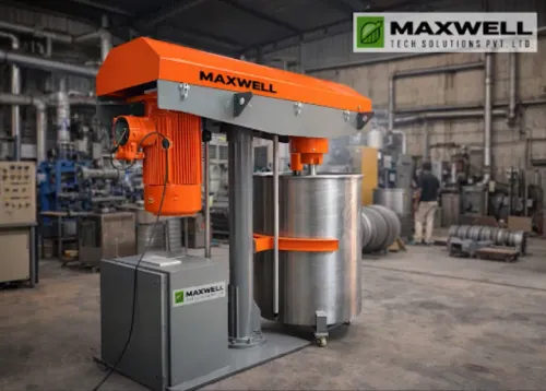
- For mixers, monitor torque or power because viscosity, fill level, temperature and solids loading can change the load at the same commanded rpm.
How to size a drive for torque, overload and operating conditions
Choose drive capacity from motor nameplate current, not horsepower or kW alone. Record rated voltage, current, frequency, base speed, power factor and star or delta connection, then compare the motor nameplate current with the drive’s continuous output current.
Select the overload rating for the duty: normal-duty drives suit predictable loads, while heavy-duty ratings cover higher starting torque and repeated overloads.
A mixer, agitator or conveyor can trip a correctly matched drive during vessel startup, product charging or a viscosity increase. Check starting torque, acceleration time, duty cycle, ambient temperature and enclosure rating before approving the selection.
A self-cooled motor can also overheat at low speed; use a separate blower, reduced torque limit, thermistor or RTD when the thermal model requires it.
Motor identification and autotuning improve control quality. Incorrect voltage, current, frequency, power factor or resistance data can cause weak torque, excess current or unstable sensorless control.
| Tuning method | Benefit | Limitation |
|---|---|---|
| Rotating autotune | Produces a more complete motor model | Requires safe shaft rotation |
| Stationary autotune | Tunes without turning the machine | May produce a less complete model |
Treat acceleration and deceleration as process settings. Short ramps can trigger current limiting, stall prevention, torque saturation, mechanical shock or DC-bus overvoltage; long ramps can disrupt batch shear or residence time. During braking, size a resistor for peak power and accumulated thermal energy, not motor kW alone.
Use regenerative braking or an active-front-end drive when returned energy exceeds resistor capability. Monitor torque or power, recipe limits and overload alarms when viscosity, fill level or solids loading changes.
How PLCs, PID loops and feedback turn speed control into process control
Speed control holds motor rpm; torque control limits or regulates turning force; position control moves and settles a shaft at a commanded location. PLC integration commonly sends a speed reference over hardwired analogue I/O or a fieldbus, while the drive handles ramping and motor control.
1. Define the controlled variable. An internal PID control loop can regulate pressure, flow or level without a separate PLC loop, but it still needs a pressure transmitter, flow meter or level sensor.
Enter the sensor range, signal scaling, filtering, deadband and engineering units correctly; a 4–20 mA signal scaled to 0–10 bar is not interchangeable with one scaled to 0–100 bar.
2. Set protection logic before tuning PID control. Add integral-windup handling, sleep and wake thresholds, sensor-failure detection and a defined fallback speed or trip. Decide whether a failed sensor stops the motor, holds the last output or selects a safe preset.
3. Treat an encoder as speed feedback, not automatic servo positioning. It improves speed regulation under changing load, while precise position control also requires suitable drive firmware, tuning, braking, encoder resolution and axis mechanics.
4. Check network behaviour before using a speed word for motion. Network update time, jitter, internal loop timing, communication-loss action and whether the reference is latched or ramped determine response; coordinated axes need a real-time motion profile, not ordinary cyclic commands.
A mixer running at fixed rpm can still produce inconsistent batches as viscosity, fill level, temperature or solids loading changes. Monitor torque or power, apply recipe limits, alarm on overload and define whether rising load reduces speed or stops the batch.
When a drive is better than a starter, gearbox or damper
Choose an AC drive when varying speed changes process output or reduces throttling losses, not merely when a motor needs gentler starting. An across-the-line starter is simple, but applies inrush current and full starting torque; a soft starter reduces starting stress without providing continuous speed control.
| Option | Main action | Limitation |
|---|---|---|
| AC drive | Varies frequency and speed | Requires correct sizing, tuning and cooling |
| Across-the-line starter | Applies full line voltage | Inrush current and fixed full-speed operation |
| Soft starter | Ramps voltage during starting | No continuous speed control |
| Mechanical gearbox | Changes speed and torque mechanically | Fixed ratios, losses, lubrication and wear |
| Damper or valve | Restricts airflow or liquid flow | Motor remains near full speed |
A mechanical gearbox suits a fixed reduction ratio or a load needing high shaft torque, but an AC drive avoids its mechanical losses and maintenance when electronic speed control is sufficient. A damper or valve can waste power by throttling a centrifugal fan or pump while the motor continues running near full speed.
For centrifugal pump energy savings, apply the affinity laws to the actual duty cycle: flow follows speed, pressure follows speed squared and ideal power follows speed cubed. System resistance, efficiency, minimum flow and time at each speed can erase the predicted benefit, so verify measured duty before claiming savings.
A drive is the wrong choice when:
- A lightly loaded motor already runs efficiently at fixed speed.
- A constant-torque load gains little from speed reduction.
- The process cannot operate below a validated speed and load point.
What an AC drives manufacturer should verify before commissioning
Before commissioning, an AC drives manufacturer should turn the motor data sheet and process brief into a checked design, not merely match kW. Provide motor kW, rated current, voltage, frequency, base speed, power factor, enclosure rating, speed range, load profile, start frequency, acceleration and deceleration requirements, ambient temperature, and process constraints.
Maxwell Tech Solutions Pvt Ltd can verify these inputs, select the control mode and overload class, and coordinate the drive with PLCs, instrumentation and protection.
| Control mode | Selection check | Consequence |
|---|---|---|
| V/f | Basic fan or pump duty with limited torque demand | Simple control, weaker low-speed torque |
| Sensorless vector | Conveyor, compressor, mixer or high-inertia starting | Better low-speed torque without an encoder |
| Closed-loop vector | Tight speed regulation under changing load | Encoder feedback improves control but adds wiring and fault management |
The design review must calculate six-pulse harmonics, including fifth- and seventh-order distortion, against transformer impedance, short-circuit ratio, drive quantity and other nonlinear loads. Harmonic mitigation may require line reactors or DC-link chokes; neither equals an active filter or active-front-end rectifier.
For long motor cables, check cable length, switching frequency, motor insulation and allowable output capacitance before fitting a dV/dt filter, output reactor or sine-wave filter. Specify shield termination, high-frequency bonding and bearing-current protection; an unbonded shield leaves common-mode current and reflected-wave overvoltage unresolved.
Finally, verify low-speed motor cooling, braking hardware and bypass logic. Safe Torque Off is not electrical isolation: define the stop category, reset, disconnect and lockout/tagout procedure. Interlock line bypass so transfer conditions do not cause inrush, a speed jump or uncontrolled process response.
Related product
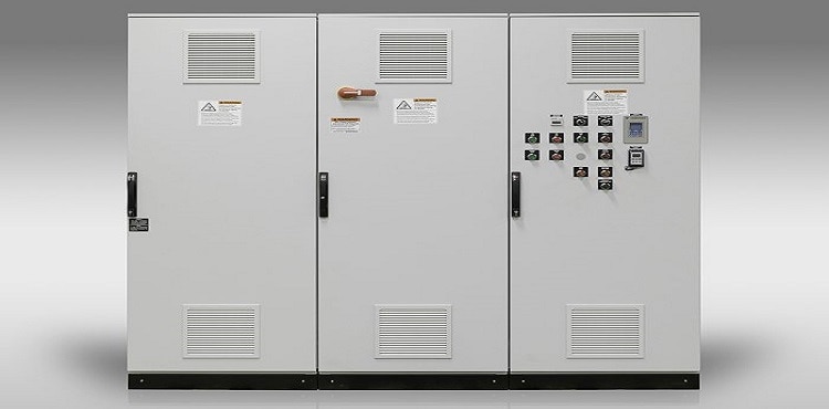 | Electrical Control Panel Manufacturer in India, Pune, Pimpri Chinchwad | Maxwell Tech Solutions Pvt. Ltd. Maxwell Tech Solutions Pvt. View product → |
Frequently asked questions
How does changing frequency control an induction-motor speed?
Synchronous speed follows Ns = 120f/P. Lowering supply frequency lowers motor speed, while reducing voltage proportionally maintains magnetic flux and limits excessive current.
How do you size an AC drive for a motor?
Check motor voltage, full-load current, base frequency, torque requirement, acceleration time, overload rating, duty cycle, ambient temperature, altitude and enclosure conditions. Select the drive using current and overload duty, not motor horsepower alone.
How do PLCs and PID loops improve drive-based process control?
A PLC can send speed references and sequencing commands, while a PID loop compares a measured process value with its setpoint and adjusts drive speed. Encoder or sensor feedback improves regulation when load changes.
When is an AC drive better than a starter, gearbox or damper?
Use a drive when you need adjustable speed, controlled acceleration, energy reduction from flow control or closed-loop process regulation. A starter suits fixed-speed operation, while a gearbox changes mechanical speed and a damper restricts flow without reducing motor speed.
What should you verify before commissioning an AC drive?
Confirm motor nameplate data, supply and motor wiring, earthing, protective devices, parameter settings, control signals, interlocks, rotation direction, ramp times, overload protection and operation under the real process load.