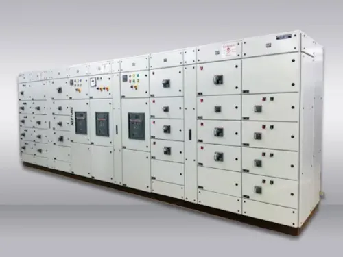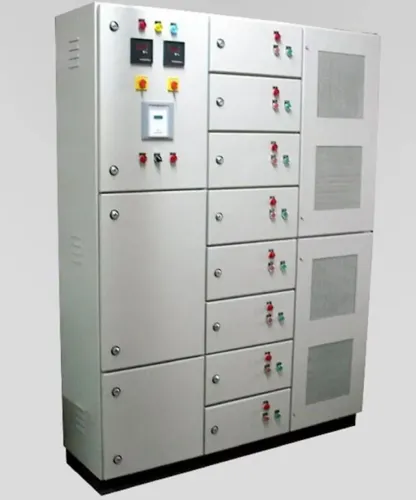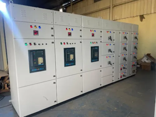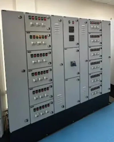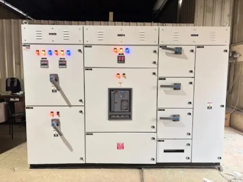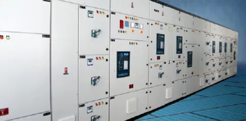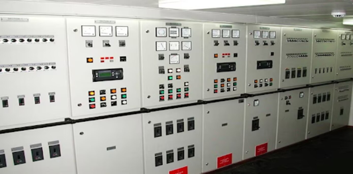
Centralized motor control brings feeders, starters, protection and motor status into one coordinated lineup, but the arrangement must match the plant’s loads, fault level, operating sequence and maintenance method. By the end, you will be able to define an MCC from a motor schedule, compare starter and construction options, and identify the design and testing work a manufacturer must complete before delivery.
Key takeaways
- Build the MCC from motor loads, starting methods and duty—not motor quantity.
- Match interrupting capacity to the calculated short-circuit current at the MCC.
- Choose fixed, withdrawable or intelligent modules based on risk and maintenance needs.
- Require tested drawings, protection settings and factory inspection records before shipment.
How an MCC Lineup Centralizes Motor Operation
Centralized motor control places the switching and protection for multiple motors in one MCC lineup. Its arrangement follows the power flow:
- The incomer accepts the facility supply, provides main isolation and protection, and feeds the internal distribution system.
- Busbars and busbar compartments carry power across the lineup while separating live conductors from feeder equipment.
- Feeder compartments connect individual outgoing motor circuits to the busbars through a breaker, fuse, contactor, overload relay, soft starter or variable-frequency drive.
- Motor-control hardware provides switching, overload protection, fault indication and control terminals for each motor.
An operator can start or stop a motor from local pushbuttons or a selector switch, or issue commands remotely through a PLC, DCS or supervisory network. The MCC returns run, trip, overload and fault status for several motors at one operating point.
Electrical and process interlocks prevent unsafe sequences, such as starting a pump before a valve is open or running two incompatible drives together.
Centralization does not remove local isolation. Each motor circuit still needs a disconnecting means at the machine or its interface; opening it must block a remote restart. Centralization also concentrates risk: a failed control power supply, network switch or common PLC interlock can stop many motors.
Critical processes need segregated sections, redundant control power or communications, and a defined manual fallback mode.
Size the MCC from the Motor Schedule, Not the Motor Count
Use the motor schedule to define each MCC feeder, not the motor count alone. Record the motor tag, motor ratings in kW or HP, voltage, phase, full-load current, starting current and inrush current, duty cycle, starts per hour, acceleration time, load torque and required control method.
One high-torque mixer can impose more thermal and starting demand than several small pumps.
- Assign one feeder per motor, then add documented spare feeders and space for expansion.
- Rate the feeder, contactor, overload relay, cable and starter for the motor’s actual duty, not only its nameplate current.
- Check aggregate heat from contactors, soft starters, VFDs, power supplies and control transformers. Ambient temperature, altitude, ventilation, spacing and simultaneous-load assumptions can reduce the usable continuous rating.
- For mixing equipment, include breakaway torque, changing viscosity, repeated starts, plugging or reversing; these conditions determine overload class and acceleration settings.
| Option | Feeder choice | When it applies |
|---|---|---|
| DOL | Contactor and overload relay | Small or non-sensitive motors where supply voltage drop and inrush current are acceptable |
| Star-delta | Six-lead motor starter with timed transition | Larger fixed-speed motors with suitable starting torque and reduced starting current requirements |
| Soft starter | Controlled voltage ramp | Fixed-speed motors needing lower starting current, smoother acceleration or reduced mechanical shock |
| VFD | Drive, bypass if required and motor protection | Variable speed, process control, frequent starts or demanding torque profiles |
A feeder’s starting current and inrush current also affect bus voltage drop and upstream protection. Specify the starter after calculating those values, not after counting motors.
Specify Protection, Fault Ratings and MCC Construction Together
Specify the incomer, feeder devices, motor starters, busbars and enclosure as one coordinated assembly. An MCCB or ACB incomer must interrupt the installation’s available fault current, while each outgoing unit must protect its cable and motor without exceeding the assembly’s short-circuit withstand rating and SCCR.
| Feature | Compare | Selection point |
|---|---|---|
| Incomer | MCCB or ACB incomer | Match voltage, continuous current, interrupting capacity and upstream coordination. |
| Feeders | MCB or MCCB feeders | Match cable size, motor full-load current, starting current and fault level. |
| Motor protection | Contactors and overload relays | Set overload protection to the motor nameplate current; verify short-circuit coordination. |
| Busbars | Rated ampere capacity and withstand | Check continuous demand, fault duty, temperature rise and future spare capacity. |
| Enclosure and segregation | Form 1 to Form 4, barriers and compartmentation | Increase segregation where an adjacent fault must not expose live sections or stop other motors. |
| Construction | Fixed or withdrawable units | Choose fixed units for lower cost and simplicity; choose withdrawable units for faster isolation, testing and replacement. |
A breaker’s interrupting rating does not establish the complete MCC’s SCCR. A lower-rated contactor, overload, terminal, disconnect or drive can limit the combination, so request tested or documented combinations rather than component certificates alone. UL 845 applies to North American MCCs; IEC 61439 verification can use testing, calculation or design rules.
Check the completed design for:
- Heat from drives, soft starters, transformers and contactors at simultaneous load, including ambient temperature and altitude.
- A local disconnect for every motor circuit, even with centralized switching and monitoring.
- Available fault current, busbar rating, enclosure rating and segregation against the specified installation conditions.
Choose the Right Architecture for Control, Expansion and Risk
Choose an MCC when several motors share a process, operators need one coordinated location, and future feeders or standardized diagnostics matter.
Keep a standalone motor-control cabinet for a small machine or isolated package; choose a PCC for plant-wide power distribution rather than motor sequencing; use a PLC panel for logic, I/O and communications, not as a substitute for motor power switching; select distributed motor-control equipment when short field runs, modular skids or high availability outweigh a central lineup.
| Option | Best fit | Main limitation |
|---|---|---|
| MCC | Multiple process motors with centralized isolation, protection, status and control | One lineup failure can affect many loads |
| Standalone motor-control cabinet | One machine or packaged unit | Expansion and plant-wide coordination become harder |
| PCC | Incomers and large distribution feeders | It does not replace dedicated motor starters and overload protection |
| PLC panel or distributed motor-control equipment | Logic, sequencing and remote I/O close to machines | Power switching, isolation and network dependence need separate design |
Centralization does not remove local isolation. Provide a disconnecting means at each motor circuit or machine interface, and do not treat network commands as emergency-stop or guard-interlock functions.
Control the shared risks by specifying:
- Segregated MCC sections for critical loads
- Redundant control power or communications where a single failure is unacceptable
- Manual or local fallback operation
- Heat calculations using simultaneous load, drive losses, ambient temperature, altitude and cooling method
For North American work, specify UL 845 when an MCC listing is required; a UL 508A PLC panel is not automatically equivalent. Arc-resistant construction contains and exhausts a defined fault—it does not remove arc-flash boundaries or energized-work risk.
What the Manufacturer Must Engineer and Prove Before Shipment
A high-interrupting-capacity breaker does not prove the MCC’s complete short-circuit rating. A contactor, overload relay, disconnect, terminal, drive or internal connection can set the limiting SCCR unless the documented combination covers the assembly.
The manufacturer must coordinate the motor schedule, single-line diagram, approved schematics, bill of materials, feeder ratings, protection settings, control philosophy and communications list. Under IEC 61439, design verification covers the bus system, enclosure, temperature rise, clearances, dielectric performance and internal connections; component certificates alone do not verify the completed MCC.
For North American work, confirm UL 845, the voltage, SCCR and construction type rather than accepting a UL 508A panel as an equivalent.
A FAT for MCC panel should use the approved documents and record results, not merely prove point-to-point wiring:
- Check feeder labels, phase identification, terminal numbers, wire ferrules, mechanical interlocks and electrical interlocks against the drawings.
- Verify breaker, overload, drive and soft-starter settings, then confirm trip and reset behaviour.
- Test insulation resistance or dielectric withstand where the specified procedure requires it.
- Confirm network addresses, PLC handshakes, permissives, diagnostics, local/remote selection and loss-of-communications responses.
- Run representative start, stop, bypass, fault and restart sequences, including simultaneous-load conditions where thermal design depends on them.
The record should also show ventilation, ambient temperature, altitude and heat-load assumptions. Maxwell Tech Solutions Pvt Ltd can support a purchaser who requires these drawings, test records and sequence demonstrations before accepting the lineup.
Related product
 | Electrical Control Panel Manufacturer in India, Pune, Pimpri Chinchwad | Maxwell Tech Solutions Pvt. Ltd. Maxwell Tech Solutions Pvt. View product → |
Frequently asked questions
How does an MCC centralize industrial motor operation?
An MCC groups motor feeders in one lineup, routing incoming power through a busbar system to starters, circuit breakers, protection devices and outgoing motor cables. Operators control motors locally or from a PLC, DCS or plant control system.
What information is needed to size an MCC?
Use the motor schedule, including rated power, full-load current, voltage, starting method, duty cycle, number of starts, feeder type, spare capacity and incoming supply details. Motor count alone cannot establish busbar, feeder or heat-dissipation requirements.
How do you select an MCC fault rating?
Calculate the prospective short-circuit current at the MCC installation point, then select equipment with a short-time or short-circuit withstand rating and interrupting capacity that meets the calculated value. Coordinate upstream and downstream protection as part of the same design.
What must an MCC manufacturer verify before shipment?
The manufacturer must check approved drawings, wiring and terminal schedules, protection settings, interlocks, busbar clearances, insulation, earthing continuity, functional operation and factory test records before releasing the lineup.