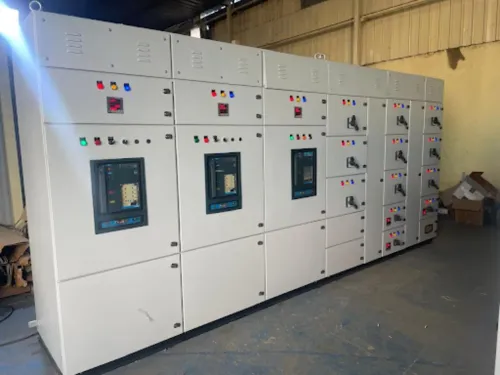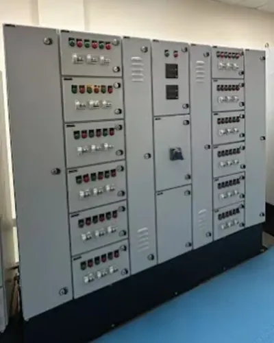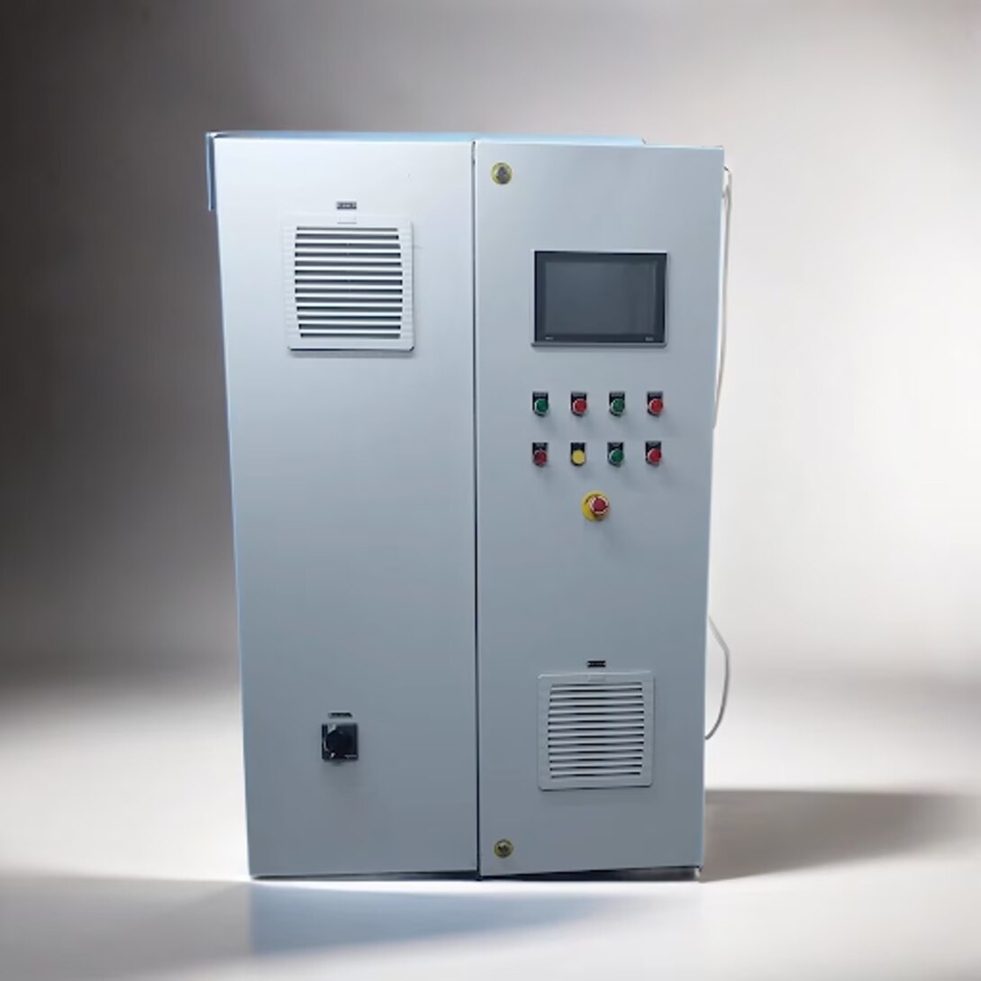
A process description such as “fill the tank, heat it, mix for 20 minutes and discharge” is not yet an automation design. You need to translate that sequence into sensors, I/O, control logic, motor interfaces, safety functions, drawings and tested hardware. By the end, you will know what to provide to a panel builder, what engineering work to expect and how to compare quotations on more than PLC brand and enclosure size.
Key takeaways
- Map every process action to sensors, actuators, PLC inputs and outputs.
- Choose PLC architecture from I/O count, signal types, safety needs and expansion plans.
- Ask manufacturers to document electrical protection, wiring, testing and panel heat management.
- Compare quotations by included engineering, components, drawings, testing and commissioning support.
How the Automation Chain Turns a Process Step into an Action
A tank-filling sequence turns a measured condition into a controlled electrical command. The industrial automation chain starts with a field sensor that detects level, temperature, pressure or position. A transmitter converts that measurement into a standard signal such as 4–20 mA, and the PLC input module receives and scales it into an engineering value.
- The operator selects Auto and enters a target level on the HMI. The PLC checks permissives such as low source-tank level, emergency-stop status and valve availability.
- If the tank level is below the start setpoint, PLC logic energises a digital output or sends a speed reference through an analog output.
- That output operates a contactor, solenoid valve or variable-frequency drive. The contactor starts the pump, the valve opens, or the VFD accelerates the motor.
- A run contact, flow switch or returning level signal confirms the action. The PLC stops filling at the target, raises an alarm if feedback is missing, and records the sequence state for the operator.
The operating device performs the physical work; the PLC only commands it. A failed transmitter, broken wire or stuck valve can therefore produce a false process condition, so diagnostics and interlocks matter.
In a conveyor, the same chain starts a motor, confirms motion with a proximity sensor, and prevents the next motor from running until the transfer point is clear.
How to Convert the Process Description into I/O and an Architecture
Turn each operating step into a cause-and-effect row, not a vague equipment name. “Fill the tank to 80%” becomes a level transmitter, analog input 4–20 mA or 0–10 V, high-level switch digital input, inlet valve digital output, and defined alarm and stop actions.
The I/O list records each tag, terminal, normal state, fail action, location, and spare point.
1. Write the sequence in order: permissive checks, start command, run confirmation, process condition, stop command, alarm, and restart rule.
2. Extract every field device and classify it as a digital input, digital output, analog input, or analog output. Add communication points for drives, scales, and networked instruments.
3. Define signal behavior. Record 4–20 mA or 0–10 V scaling, engineering units, cable destination, and what an open wire or out-of-range value must do.
4. Treat load-cell wiring as part of the architecture. Specify shield termination, grounding topology, separation from VFD and contactor conductors, stable excitation, calibration records, and open- or short-circuit diagnostics.
5. Mark safety-related signals separately. A safety PLC does not make ordinary I/O safety-rated; the complete sensor, logic, output, feedback, and wiring path must meet the risk-assessed PL or SIL.
Choose the PLC arrangement from point count, distance, expansion, motion, and network requirements:
| Option | Best fit |
|---|---|
| Compact PLC | Small machine with local I/O |
| Modular PLC | Growing system needing expansion |
| Remote I/O | Distributed equipment or long cable runs |
| PLC plus VFDs | Speed control, motor feedback, and drive diagnostics |
What the Manufacturer Engineers Beyond the PLC Program
A usable panel begins with engineering documents, not ladder logic. The control philosophy defines operating modes, permissives, interlocks, alarm responses, manual control and restart behaviour. A single-line diagram shows incoming power, isolation, protection, the MCC and PCC interfaces, while the I/O schedule ties every field device to a terminal, module, signal range and spare point.
Add terminal plans, cable schedules, panel layouts and an HMI SCADA tag and alarm list.
| Layer | What the manufacturer engineers | What failure looks like |
|---|---|---|
| Power | Disconnecting means, overcurrent protection, protective bonding and control-circuit protection to IEC 60204-1 | A logically correct PLC leaves the machine unsafe or impossible to isolate |
| Control | PLC, HMI SCADA, drives, MCC/PCC interfaces, alarms, recipes and communications | Operators cannot diagnose faults or control equipment consistently |
| Safety | Risk-based PL or SIL architecture using safety relays, safety PLCs, monitored contactors and feedback | A standard PLC routine is mistaken for a safety function |
| Security | Asset inventory, zones and conduits, least-privilege accounts, backups and controlled remote access | A password-only HMI exposes the whole control network |
A safety PLC does not make every connected input safety-rated. Sensors, logic solver, wiring, output devices, feedback monitoring and diagnostics must together achieve the required performance level. The FAT should prove point-to-point wiring, labels, safety trips, simulated faults, network addresses, drive parameters, alarm behaviour, sequence transitions, drawings and backup files.
IEC 62443 also assigns lifecycle duties: the supplier documents secure configuration, while the plant owner governs users, remote access, patching and maintenance.
What Information and Electrical Design Checks the Panel Requires
Before drawing the enclosure, specify the supply voltage, phase and frequency, available fault level, motor ratings, starting method, I/O list, network protocol, cable lengths, ambient temperature, enclosure location and required IP or NEMA rating.
- State whether drives need braking resistors, line reactors, output filters or bypass starters.
- Identify hazardous-area constraints, emergency-stop functions and the required Performance Level or SIL.
- Define HMI access, user roles, remote connections, backup ownership and approved industrial protocols.
- Confirm spare capacity for I/O, terminals, cabinet space and future heat load.
SCCR is an assembly-level rating, not simply the main breaker’s interrupting capacity. The marked SCCR must meet or exceed the installation fault level, based on permitted combinations of breakers, contactors, starters, VFDs and other components.
A VFD needs more than a replacement for a starter. Check motor-cable routing, shielding, grounding, bearing-current mitigation, braking-energy disposal and VFD EMC harmonics. Never connect power-factor correction capacitors to a VFD output; coordinate line-side correction and harmonic filtering with the drive instructions and facility system.
Choose cooling from calculated losses, not cabinet size alone. Add PLC supplies, transformers, drives and contactors, then compare that heat with ambient conditions and the enclosure’s cooling method.
| Cooling method | Strength | Design risk |
|---|---|---|
| Natural convection | No moving parts | Limited heat removal |
| Filtered fan | Higher heat removal | Filter maintenance and enclosure-rating impact |
| Air conditioner | Strong temperature control | Condensation, service and power demand |
A safety PLC does not make ordinary I/O safety-rated. Verify the complete safety function, including sensors, logic, outputs, feedback and wiring diagnostics. Use segmented networks, managed switches, role-based accounts, disabled unused ports and controlled remote access.
How to Compare Panel Quotations and Verify the Finished System
A useful PLC panel quotation comparison starts with matched scope, not the lowest total. Give every bidder the same I/O list, load schedule, network specification, enclosure rating, drawings, spare capacity and test requirements.
| Offer item | Compare | Require as evidence |
|---|---|---|
| PLC and I/O | Brand, memory, expansion, 20% spare capacity | I/O schedule and datasheets |
| Panel compliance | IEC 61439 design verification, short-circuit rating, temperature rise | Verification records, not only inspection notes |
| Safety | Disconnect, protective bonding, overcurrent protection and emergency-stop architecture | IEC 60204-1 checklist and circuit drawings |
| Testing | Factory acceptance test (FAT) scope and witness conditions | Signed results, defect log and retest record |
At the factory acceptance test, operate every input and output point, check terminal and device labels, simulate sensor and communication faults, verify drive parameters, alarms, recipes, sequence transitions and network addresses. Collect the approved drawings, PLC and HMI backups, passwords, cable schedule and change list before shipment.
- Confirm the delivered panel matches the approved schematic, component ratings and short-circuit withstand rating.
- Verify protective-bond continuity, insulation or dielectric tests, emergency-stop removal of hazardous motion and accessible isolation for lockout/tagout.
- Check that remote access, user accounts and backups follow the agreed IEC 62443 responsibilities.
Ask Maxwell Tech Solutions Pvt Ltd to price deviations separately; otherwise a cheaper offer can hide omitted terminals, testing or documentation. Reject unresolved FAT failures, undocumented substitutions and any panel whose logic works but cannot be safely isolated or maintained.
Related product
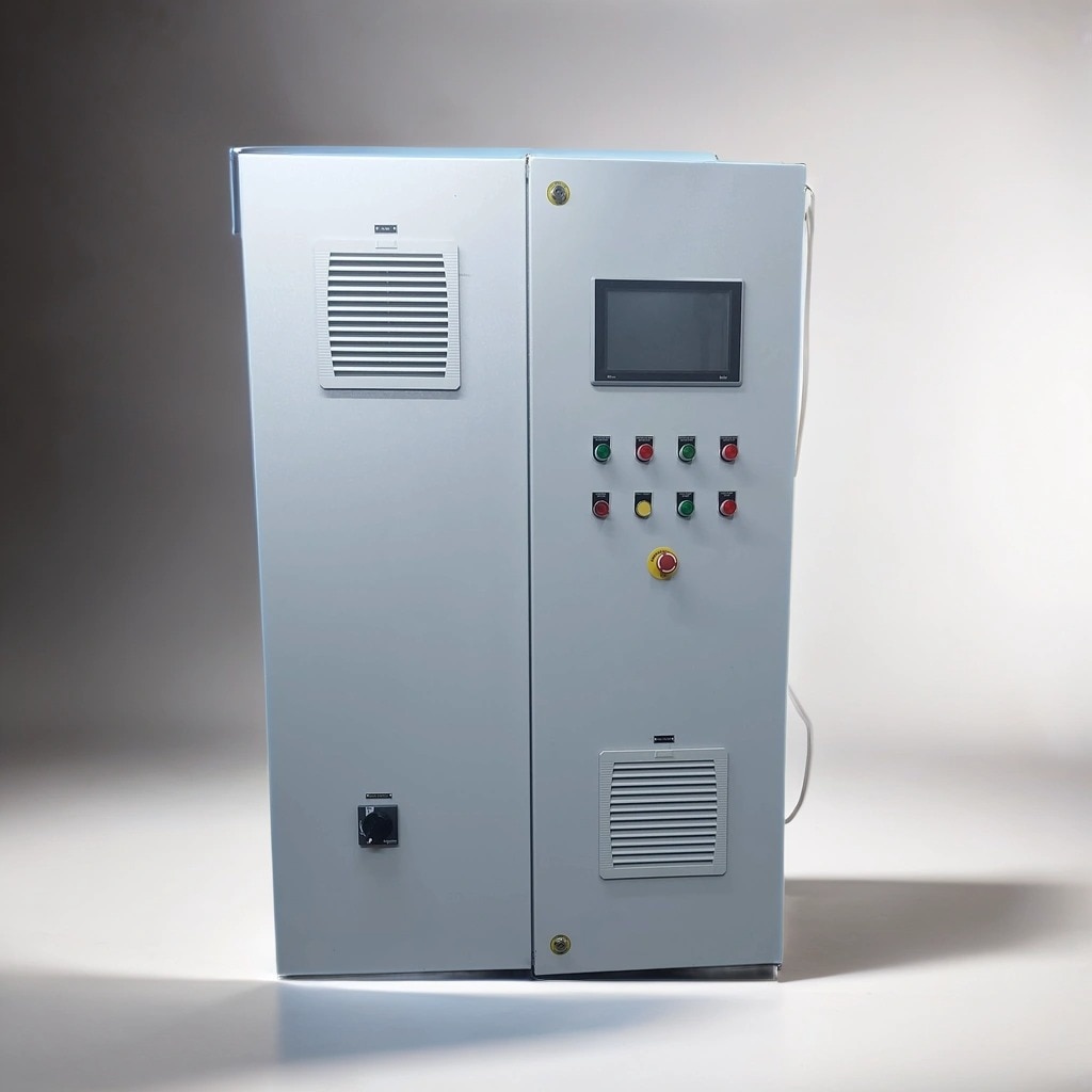 | Electrical Control Panel Manufacturer in India, Pune, Pimpri Chinchwad | Maxwell Tech Solutions Pvt. Ltd. Maxwell Tech Solutions Pvt. View product → |
Frequently asked questions
How does a PLC control panel turn a process step into an action?
A sensor detects a condition, a transmitter sends a standard signal, and the PLC scales that input before logic commands an actuator through an output circuit.
How do you convert a process description into PLC I/O and architecture?
List each measurement, command, alarm, interlock and actuator, then assign signal types, I/O points, safety functions and network requirements before selecting the PLC architecture.
What does a PLC panel manufacturer engineer beyond the PLC program?
The manufacturer engineers power distribution, protection, motor starters or drives, wiring, enclosure layout, heat management, safety circuits, communications and documentation.
What should you check when comparing PLC control panel quotations?
Check the I/O schedule, component makes and ratings, short-circuit protection, enclosure details, drawings, factory testing, commissioning scope and included spares.